ORIGINAL RASTER PLATE / VESSEL

Whole-vessel systems overview

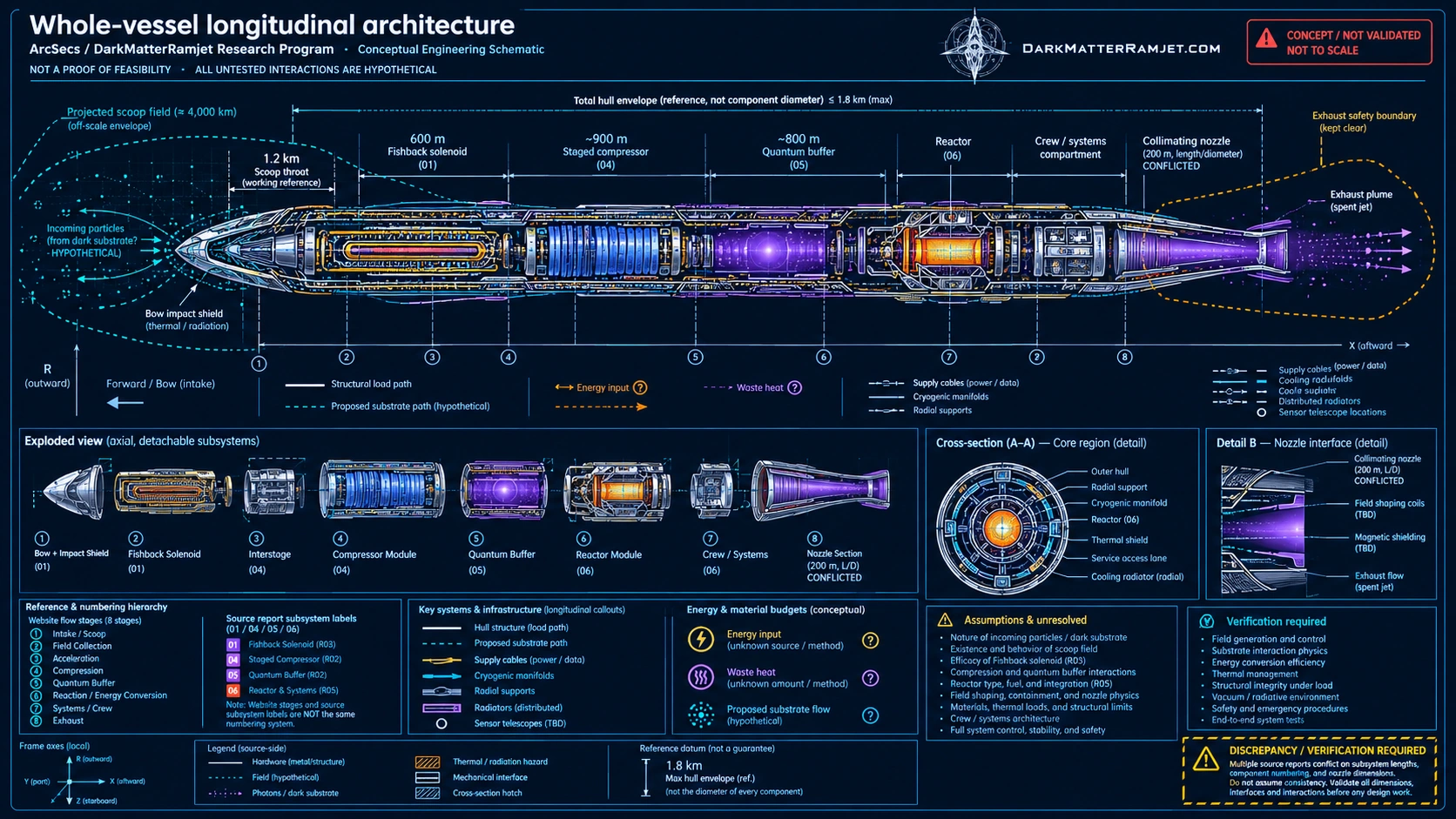
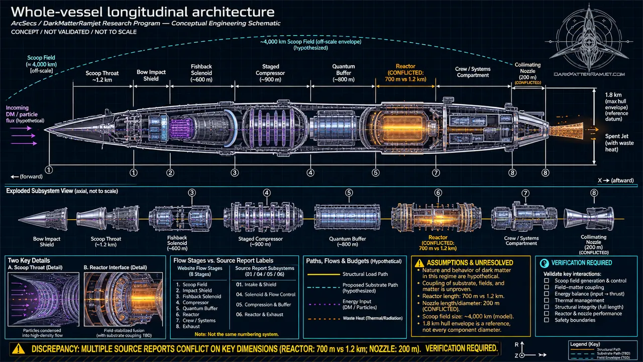
A single visual map of the proposed vessel and its principal functional sections, from the forward collector to the aft exhaust.

USER-SUPPLIED CONCEPT DRAWING · NOT VALIDATED ENGINEERING
Full technical concept plate depicting Whole-vessel systems overview with labeled sections, diagrams and source-proposed annotations
Whole-vessel systems overview / author-supplied original resolution; web-optimized raster derivative.Open full-resolution image ↗ · Save web image ↓
01 / THE PRINCIPLE

What this assembly is supposed to do

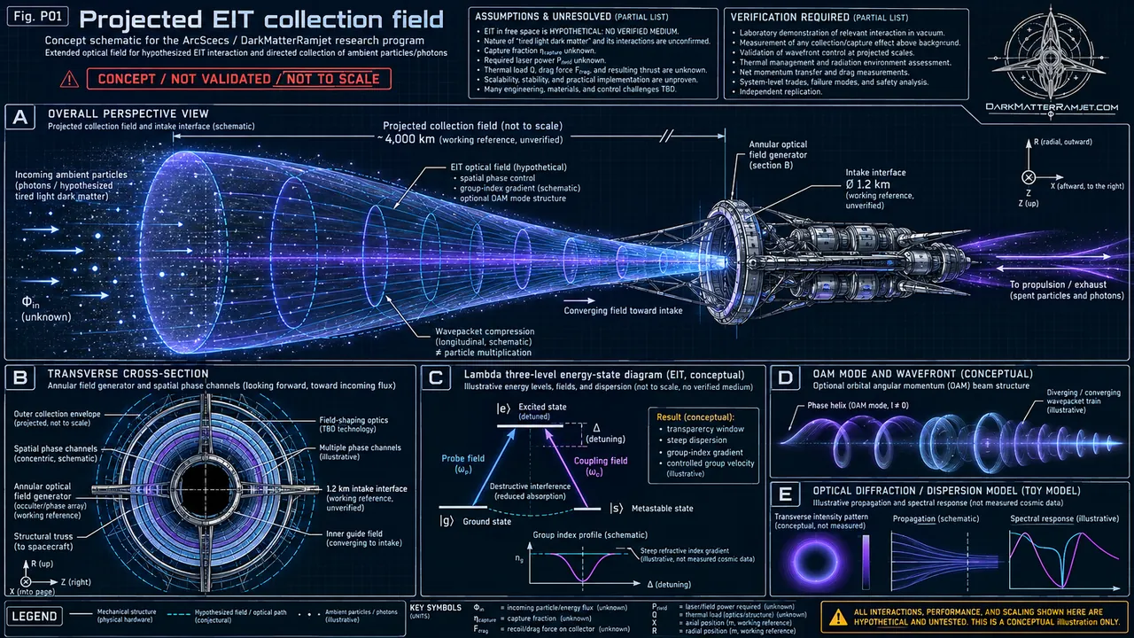
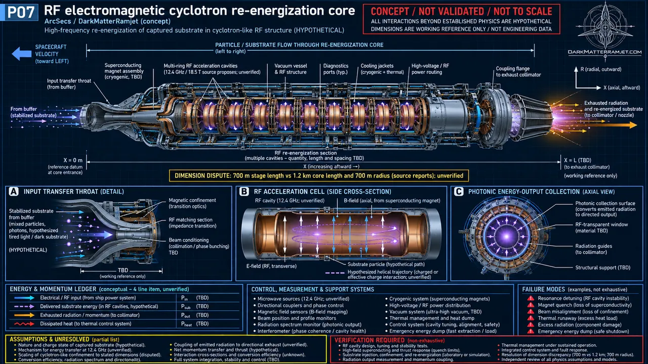
The project uses a ramjet-like through-flow architecture: hypothetical low-energy substrate is captured, guided into the hull, conditioned, stored, re-energized and expelled. Power distribution, heat removal and control hardware must support this sequence.

02 / CONNECTIONS AND BOUNDARIES

How it fits the engine

This drawing is a navigation overview, not a dimensionally verified general arrangement. Subsystem dimensions in the reports disagree; the section order reflects the educational eight-stage model.

OPEN VALIDATION QUESTION

Can each section fit inside a consistent 6.4 km outer envelope with maintenance access, shielding, power and heat-rejection volume?

THE JOURNEY STARTS WITH A QUESTION

Ready to see the flow?

Enter the interactive lab and explore the eight proposed stages.

Launch the simulator ↗